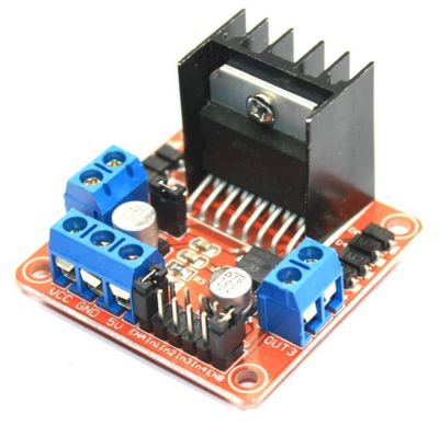


We are going to make a little program that moves the motors in both directions, forward and backward, and in opposite directions of each other, also varying the speed of movement. Now we are in a position to start programming. The assembly scheme that we are going to use is going to be the following one, although you can use the pins that you want whenever we respect that those that we connect to ENA and ENB are PWM. If we have the jumpers in place, the motors will rotate at the same speed. We will connect them to two Arduino PWM outputs so that we send a value between 0 and 255 that controls the speed of rotation. To control the speed of the motors we have to remove the jumpers and use the ENA and ENB pins. And the same with pins IN3 and IN4 and engine B. They work so that if IN1 is at HIGH and IN2 at LOW, motor A turns in one direction, and if it is IN1 to LOW and IN2 to HIGH it does to the other. The pins IN1 and IN2 are used to control the direction of rotation of the motor A, and the pins IN3 and IN4 of the motor B. If it were not so, we would have to reverse the connections. Keep in mind the polarity when connecting them, so that when later we make them move forward, they work as they should.

The outputs for engines A and B will give us the energy to move the engines. In this session we are going to focus on the control of DC motors. The other connections are used in one way or another depending on whether we are going to drive two DC motors or a stepper motor.
L298N MOTOR DRIVER DRIVER
The L298N H-bridge driver board module allows us to control the speed and direction of two DC motors or a stepper motor in a very simple way, thanks to the 2 H-bridge it is mounted on.


 0 kommentar(er)
